Sunday, September 18, 2016

Lower aeroshell finale: Part

If you've stuck with me this far, you're familiar with the overall strategy for fabricating the HAPP's outer aeroshell: Make the plug, then the mold, and finally the part. Well, after perhaps 250 hours of study, experimentation, failures, and troubleshooting, here we are at last at the part-making stage. Let's get busy.

First, let's start with the end in mind. Below is a picture of the part we're making - the lower aero shell. Recall that the HAPP is essentially a scale model of the Apollo Command Module. The lower aero shell is analogous to the lower heat shield on the Command Module. Of course, the HAPP will not experience the blow-torch heat that the CM felt upon reentry at Mach 32, but we desire aerodynamic stability at supersonic and trans-sonic speeds, and the Apollo design achieves this. (Interesting technical footnote: Blunt shapes experience less heating upon reentry compared with pointy shapes. This was a military secret until NACA, the predecessor of NASA, finally published it in 1958. Read it here.)

If you just came here for a sexy picture of the finished product then you're done. See you next post. If you care to see how the sausage is made then proceed!


Finished lower aeroshell.
Mold parting line is visible and will
be sanded out and polished.
This part is 1 meter in diameter.

Lookin' like a BOSS with that Kevlar/carbon
fiber weave on the A-surface


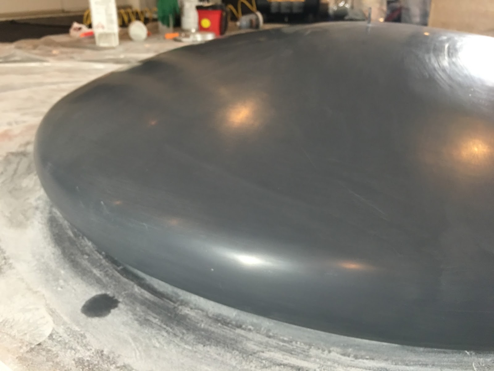
OK so here we go. Below are two pics from my first attempt at the full-scale finished part. The left frame shows the beginning of resin infusion - recall that we're using the vacuum infusion process I described previously. The portion that's been wetted by resin is darker than the surrounding material.

The right frame shows the "finished" part - a total disaster! The resin did not thoroughly infuse around the part, and there was a lot of raw fiber that I had to cut away. You can still see loose fiber around the edges. In addition, the layup consisted of only two layers of fabric, and it did not provide sufficient rigidity. The part is quite floppy and feels a bit like leather. Very expensive and useless carbon fiber leather, that is...


Trial #1: Total failure!


So onward to trial #2 with lessons learned.

The first process improvement involved the PVA. Recall that this is a non-stick coating sprayed onto the mold surface so the layup and resin don't adhere to the mold. In trial #1 the PVA pooled in the bottom of the mold. In trial #2 I drilled a drain hole and let the excess PVA flow out. This resulted in a highly uniform coating inside the mold.


PVA drip hole and uniformly-coated mold.
Mold legs were amputated to facilitate
covering the entire mold with the vacuum bag.
Easy come, easy go.


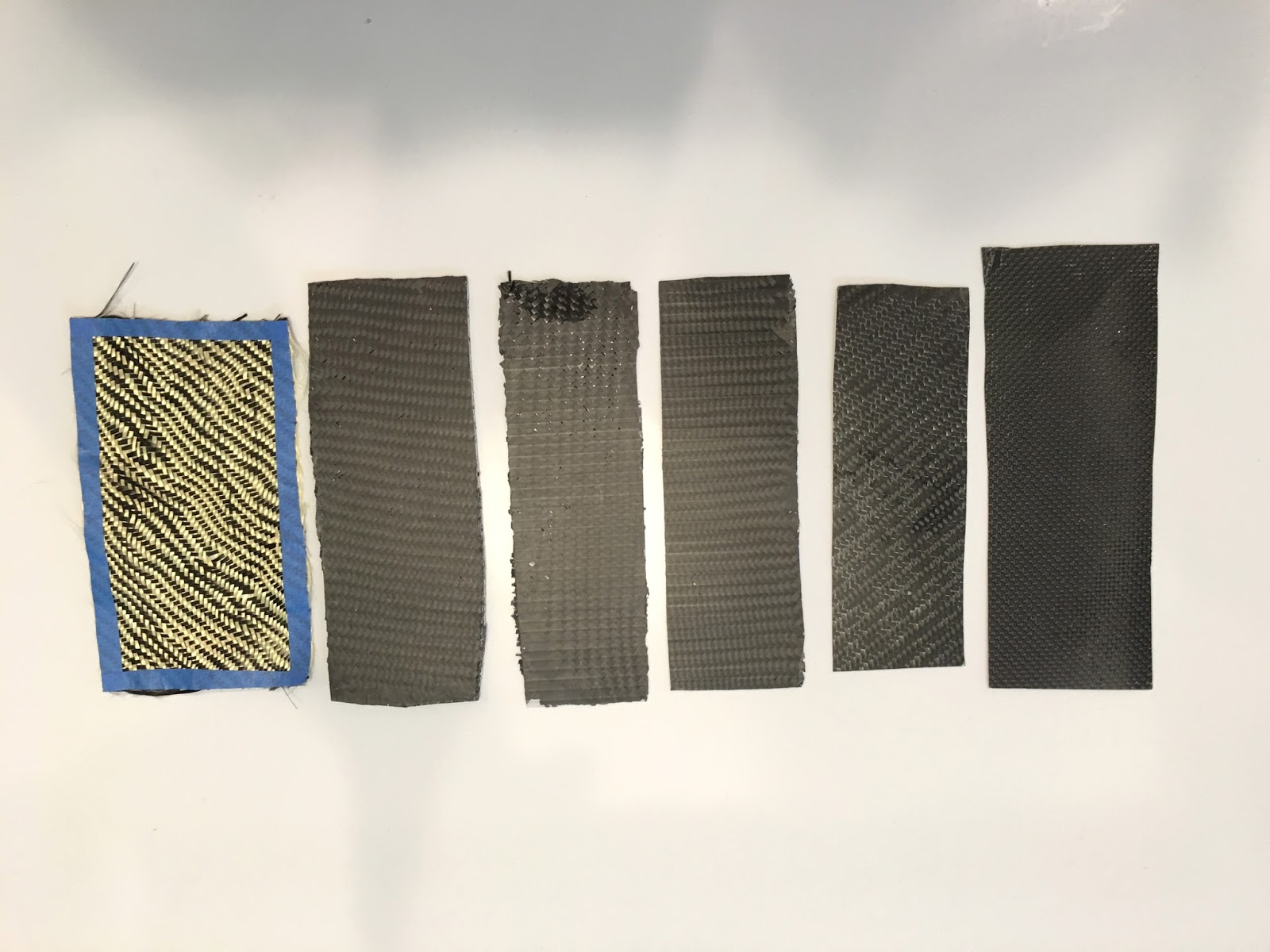
Next came the layup. The main improvement over trial #1 was to add a third layer of fiber and an intermediate layer of Lantor Soric foam core. This improved layup was developed in the previous post.


Clockwise from top left:
Kevlar A-surface layer;
3K carbon twill;
Lantor Soric foam core;
3K carbon plain weave B-surface.


Here's a view of the first three layers. I trimmed the excess overhanging material before bagging and infusion.


Working on the layup


For the outlet port I wrapped a spiral plastic tube with permeable nylon peel ply, ran it around the lip of the mold, and connected it to the vacuum pump. This provided an even vacuum draw all around the part.


Nylon-wrapped spiral tubing (green) on mold lip.


Next I placed the entire mold in a vacuum bag and affixed the inlet ports. For the bagging material I used a very elastic sheeting called Stretchlon 200. And below you can see the final major improvement versus trial #1 - the addition of more inlet ports. This allowed for faster resin flow and more even coverage around the part.


4 resin inlet ports

At last it was time to infuse. After activating the vacuum pump I opened the resin valves and established an even flow. Below is a short video that gives you a sense of the flow speed. This is 3/4" outer diameter plastic tubing. In the future I will eliminate the bubbles by de-gassing the resin in a vacuum tank prior to infusion. For this first aeroshield, which will be sacrificed in flight testing, the bubbles won't affect the final part significantly.


With the additional resin inlet ports, infusion progressed evenly and quickly.


Infusion progress

I also discovered that the infusion ports needed constant support. With the help of a friend (thanks John!) we quickly improvised the support "lattice" shown below. In future builds we'll use an actual lattice.


Resin feed tubes clamped in place

Infusion: Done. Resin cure: Done. Now it was time to decant the mold from the vacuum bag. It was a little tedious and some helping hands made for fast work.


Decanting from the vacuum bag.
Chunks of red flow media are visible.

Below is the decanted part and a close up of the B-surface. Remember that the B-surface is not normally visible and its appearance is not critical. Nevertheless, the surface doesn't look too bad. You can clearly see the imprint of the red flow media that sat on top of the layup.


B-surface detail

Finally, after a couple of hundred hours of learning and failures, it was time for the coup de grace: De-molding of the finished part. That's me in the left frame below with a big smile on my face because the part looks good. John is holding the part in the center frame with half of the mold removed. The right frame shows the part and A-surface in all its Kevlar glory.


De-molding the part

This picture says it all. Success!


Thanks for helping, John!


Here's a view of the part being rotated so you can get a better sense of the shape and dimensions. There are a few tasks for later - Trim the edges, fill in a few minor defects, and polish the outer A-surface.


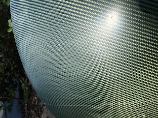
And here's some of the A-surface detail. Kevlar, beautiful Kevlar... the mold parting line is clearly visible in this picture. I will sand it out and polish later.


A-surface detail

Here's the lower shield in the approximate position it will maintain on the HAPP. I'll do a post about the mounting system later. There is an upper aeroshell as well - pics to follow soon.


The lower shell goes here

And once again, here's the finished part. I essentially spent the entire summer learning to fabricate an aerospace-quality composite aeroshield. It was far more work than I expected, but it was a fantastic learning experience and the part turned out better than I expected.


Aeroshell... beast mode

During this final trial (#2) I noted many process refinements for future production runs. My friend John provided many of the more useful observations and ideas. There are also a few small quality issues with the part that need to be ironed out but the process refinements should fix them.

Undoubtedly I will make a few more parts in the future as we test & destroy before the first mission flight. With some luck, the process will only get easier and the parts will be even higher quality.

Onward!

Lower aeroshell part 3: Composite design

With the plug and mold fabricated, the next step is to figure out what type of composite material to use. This is an entire field of engineering unto itself. Composite materials typically consist of a resin matrix surrounding some sort of fiber, usually carbon, fiberglass, or Kevlar.

There are a variety of resins available and they generally fall into one of three categories: Epoxy, polyester, or vinyl ester resins. Each has pros and cons, but for lightweight aerospace parts, epoxy is a good choice. After playing around with all three resin types, I settled on an epoxy called CLR from Rock West Composites. It has attractive mechanical properties and it contains a UV inhibitor that protects the Kevlar fibers we're going to use from harsh sunlight at high altitudes. It also cures to a nearly clear appearance rather than the yellowish tint found with many other resins. If we're going to do this thing, we might as make it look good - don't want to hide those beautiful carbon and Kevlar fibers!

As for the fibers, I decided to use carbon for its strength-to-weight properties, but I also wanted to add some impact protection to the outer layer of the bottom aero shield. The parachutes should bring it down slowly enough, but there's always the chance of landing on a sharp rock. To achieve this impact protection, I decided to use a kevlar-carbon fiber blended weave.

Kevlar makes a nice outer layer because the shell is convex. This means the shell's outer layer will be in tension when it impacts the ground. Kevlar is extremely strong in tension, but doesn't like compression as much when used in a composite structure. Therefore, the inner layers should be carbon fiber. The remaining question is: How many layers of fiber are necessary to reinforce the Kevlar and give acceptable strength for minimum weight?

After a few rough calculations it was time to experiment. I made several small samples with various numbers of carbon fiber layers and intermediate reinforcing materials. The process I used is called vacuum infusion and it's the same type of process I will use to make the final aeroshield. Alternative methods are hand-layup with vacuum bagging and pre-pregnated fiber with an autoclave. Vacuum infusion can almost achieve the low resin weight content of pre-preg (around 40%) but without the added complexity and expense of having to use an autoclave.

In short, vacuum infusion entails placing the layup - the stack of fiber materials - into an airtight plastic bag. At one end of the bag is an inlet port. At the other end of the bag is an outlet port. The inlet port is connected via plastic tubing to a pot of liquid resin. The outlet port is connected to a vacuum pump. When the pump is activated, resin is drawn into the layup and infuses thoroughly throughout all the fiber layers. Because the interior of the bag is a vacuum and the exterior is exposed to the atmosphere, the layup experiences 1 atmosphere of pressure (14.7 PSI, 101KPa) and the layup is compressed strongly. Because of this, the layup does not retain excess resin. The excess is drawn out of the outlet port and into a trap for disposal.


Carbon fiber layup ready for vacuum infusion.
Inlet (resin) and outlet (vacuum) ports are visible.

Contents of the vacuum bag:
Stiff backing board (white).
Carbon fiber (black).
Peel ply (green) - removed after infusion.
Flow media (red) - removed after.
Absorbent batting (white) - removed after.
Vacuum bag (purple).
Tacky tape (grey) - to seal the bag.

The main decision is how many layers of fiber are necessary. Below you can see some samples I made. The left-most sample is just a raw piece of Kevlar fabric with no resin to show the contrast in appearance versus pure carbon fiber. The other samples have 1, 2, or 3 layers of fiber, and some also have a foam core called Lantor Soric


Various layup combinations for testing

After testing the stiffness and strength of these layup samples, I selected a layup consisting of Kevlar/carbon weave for the outer layer, a 3K carbon fiber twill, Lantor Soric, and a 3K carbon fiber plain weave for the inner layer. The outer layer is the "A surface" (to use a term from the automotive industry) and will be visible. It needs, therefore, to look awesome! The inner layer is the "B surface" and the final finish and appearance are not critical.

This layup might be overly-strong for the HAPP lower shield. If so, we might be able to eliminate one of the layers (probably the Lantor Soric) and further reduce the weight of the part.

Let's make one and see!

Monday, September 12, 2016

Lower aeroshell part 2: Mold

Recall from the last post our 3-phase process for fabricating an aerospace-quality, carbon fiber aeroshell to serve as the "skin" of the HAPP:

  1. Make a scale model of the aeroshell. This is known as a plug.
  2. Using the plug, make a fiberglass mold that's a negative image of the model.
  3. Using the mold, form the various layers of carbon fiber and other materials to create the actual part that will fly on the HAPP.

Last time we wound up with a nice, smooth, and shiny plug, finished off with a glassy epoxy coating. In this post I'll take you through creation of the mold. I found the instructional videos and reading material at Fibre Glast, Rock West Composites, and Easy Composites to be especially useful.

And quick props to the guys at Fibre Glast - I purchased most of the materials for the final mold and parts from them after trying other suppliers for various prototypes. Fibre Glast has super fast turnaround and their products are great. Thanks guys!


Shiny plug, ready to create the mold

We'll create the mold in two halves so we can open it up to extract the plug, and later, the parts.

The first step is to add some temporary barrier features around the plug using white plastic corrugated signboard. One barrier goes across the plug diameter on the outer surface. This will allow forming of a fiberglass lip to mate with the other half of the mold. Another barrier goes around the plug and sits flush on the mounting board. This will allow forming of a fiberglass flange that will be quite useful once we start forming actual parts. (Spoiler: The flange is for attaching a vacuum bag with tacky tape. Don't worry, we'll get to that later.)

Here's the plug with barriers affixed using pink styrofoam and hot glue.


First half of mold to be formed on side
opposite from the pink styrofoam

The second step is to prepare the plug surface. Why, you ask, do we need to do any more than the tedious repetitions of coating, filling, and sanding that we performed already? Because the resin we'll use to make the mold will bond with the plug's grey gel coat unless we first slather it with appropriate release agents.

Here we'll use 4 coats of mold release wax with an hour of drying time between the second and third coats. Then we'll spray it with a thick layer of polyvinyl alcohol (PVA) release agent and let it dry for a few hours. PVA is a water-soluble (but not resin-soluble!) chemical that dries to form a thin green film between the plug and mold. This film can be easily peeled off when we're done. Here's the plug with PVA sprayed on one side, just prior to creation of the first half of the mold:


Green slime time with PVA. The beige
balls of clay are registration dots that
will form features to seat with the other
half of the mold.

Now it's time to fabricate. First I paint the PVA with orange tooling gel coat, similar to the grey gel primer I used on the plug. The orange gel coat will ensure a smooth surface on the mold face as I build up the structural layers of fiberglass behind it. The orange color also helps to show surface imperfections so the mold can be properly conditioned. Plus it looks kinda cool.

When the orange gel coat starts to cure and get tacky (I used 2% MEKP catalyst) then it's time to start laying up some glass. The first layer is a 2-ounce plain weave glass. This fabric prevents print-through of the heavier layers behind it. The next two layers are 20-ounce tooling fabric. I wet all the layers with isophthalic polyester resin using a paint brush and small roller to work out the air bubbles. After curing, the first half of the mold looked like this.


Tilted for a reason....

You may notice I didn't take any particular care to create an aesthetic pattern with the fabric layup - I was only concerned with functionality and strength. You may also notice the base board is inclined about 45 degrees. This is to ensure the wet fiberglass drapes down around the outer edge of the plug using the force of gravity. Otherwise the glass would droop away from what would otherwise be an undercut radius.

At last it's time to remove the mold and see what we've accomplished. Here's the first half of the mold immediately after coming off the plug. I've peeled away the layer of PVA and I'm starting to trim up the edges with a Dremel.


Doesn't look so pretty now but just wait!

With the first half cleaned up, it goes right back onto the plug, which is now tilted in the other direction to create the second half. We repeat the same process - wax, PVA, orange gel coat, 2-ounce fiberglass, then two layers of 20-ounce fiberglass. Allow an overnight cure.


Wax/PVA, orange gel coat, fiberglass

Now for the finishing touches. After cleaning up the second half of the mold, I assemble the two halves together using some #10 bolts. I also fiberglass on some legs to stabilize the mold as I fabricate parts.


Bolts and legs

Finally, I fill in the small gap between the mold halves with automotive body filler, and finish the entire surface by sanding with a progression of #120 to #2000 grit paper. As a finishing touch I buffed the surface with automotive rubbing compound.


The finished mold surface. Ready for parts.
The outside is ugly but the A-surface is pristine.
It has it where it counts!

Whew! Another 50 hours at least. Now to figure out what kind of carbon fiber composites to use... next post!

Sunday, September 11, 2016

Lower aeroshell part 1: Plug

It's been a long hot summer, and it may seem from the lack of blog updates that the project has petered out. Not true! I've spent the summer learning how to fabricate aerospace-quality custom carbon fiber shells to use as the aerodynamic body of the HAPP. This is the "skin" that will cover the carbon fiber "skeleton" I developed earlier.

It took a lot of trial and error and a lot more time than expected. I estimate I've got over 250 hours invested in various trials, most of which ended in failure. Sure, I could have paid thousands of dollars to have a professional fabricator do the work, but where's the fun in that? Plus, I picked up a few more 21st century fabrication skillz.

In the end it boiled down to this. I selected the following method of fabrication:

  1. Make a scale model of the aeroshell. This is known as a plug.
  2. Using the plug, make a fiberglass mold that's a negative image of the model.
  3. Using the mold, form the various layers of carbon fiber and other materials to create the actual part that will fly on the HAPP.

So it's going to be plug, mold, and part. Ready? Here's the plug...

Plugs are useful because it's often easier to shape or sculpt a model of the part rather then try to directly create a negative-image mold. The plug can be made out of a variety of materials, such as styrofoam, wood, or clay. I know, because I tried them all!

The final plug I used consisted of a wood skeleton covered with automotive styling clay. The wood pieces were cross-sections of the desired shape. I cut the main outer radius of the cross-sections using a router mounted to a giant protractor.

In this photo you can see the outline of the entire aeroshell  - it's a scale model of the Apollo command module from the 1960s. I chose this shape due to it's known stability in supersonic flight regimes. This is important because the HAPP will go supersonic as it descends in free-fall after the balloon bursts at 30Km altitude, only to slow down as it descends to thicker atmosphere.


Giant protractors rule!

As the aeroshell will be fabricated in two pieces - a lower "heat shield" and an upper shell - I separated the heat shield cross-sections from the uppers and mounted them on a base board. This was the first step in shaping the plug.


Cross-sections mounted, I tried to fill in as much of the volume as possible with cheap fiberglass and expanding polyurethane foam. I could have filled it all in with clay, but good clay is quite expensive and also heavy - it probably would have required over 200 pounds of clay had I not used glass and foam.

One little trick I developed was to include a small steel shaft in the center of the plug. This provided an axis about which I could rotate a wooden guide fixture and confirm whether the finished profile is correct. You can see this guide fixture in the following image.


Clockwise from top left:
(1) Laying fiberglass over wood cross-sections.
(2) Wetting out the glass with resin.
(3) Checking glass profile versus target profile.
(4) Filling out the volume with polyurethane.

Next came the surface clay and final shaping. I tried a variety of modeling materials and had several false starts.


Some good, some not so much

After good advice from a friendly professional automotive designer (thanks, Richard!) I settled on Autostyle Clay by Chavant. It can be shaped, machined, and coated. However, before forming the clay, it does need to be warmed up over 100F (40C) or so, which I accomplished using the kitchen oven.


Baking some tasty treats

Bit by bit the clay went on. I pressed and formed the clay into the desired shape, constantly checking and scraping clay with the wooden guide fixture mounted on the central steel shaft. This fixture rotated freely and allowed me to confirm the profile was precisely correct.


Clockwise from top left:
(1) Filling out the profile with clay.
(2) Scraping with the wooden fixture.
(3) Lots of bits after scraping!
(4) Ready for coating.

The last phase of preparing the plug entailed getting a smooth, glassy, and hard epoxy gel coat onto the clay. The gel coat gives a durable surface for creating the fiberglass mold. To do the gel coat right requires multiple coats. I applied three coats with a compressed air spray gun. In between coats, I filled in low spots with automotive body filler and then sanded with a progression of grits from #180 to #2000. Eventually the surface attained a nearly-flawless look and feel which I enhanced by buffing with automotive polishing compound.

To orient yourself, note that you're looking at the bottom of the craft. This would be the heat shield on an Apollo capsule. The plug is approximately 1 meter in diameter.


From the top, each row shows successive layers
of gel coat with filler (reddish color) and the
result after sanding to a fine finish.

At last the plug was ready and I could progress to the mold fabrication phase. This blog post may read like a nice linear story, but it encompasses perhaps 100 hours of reading, trial and error, and tedious model construction. It was fun to do... once.

Next post: Fabricating the mold.

Sunday, July 31, 2016

More inspiration

Work on the carbon fiber and kevlar aeroshell continues. It's been harder than I thought, but I'm making progress.

In the meantime, here's some more of my aerial photography for inspiration. This one was taken from airline cruising altitude over Alaska. I plan to go more than 3 times higher with the HAPP - about 25% higher than a U2 spy plane!


Tuesday, July 12, 2016

Structure: Initial design

My blogging has slowed down recently but the HAPP project has not! Among other things, I've been working on the main structure for the flight hardware, as I'm not going to try and fly the plywood and cardboard prototypes I've been using for the early development work.

The punchline first: Main internal structure is complete. Here's the overall view. To get an idea of the finished HAPP, imagine an Apollo Command Module capsule wrapped around this carbon fiber skeleton. A big rounded "heat shield" goes on the bottom (for the HAPP, an impact shield) and a conical section rises from the jet arms up to the apex.


Finished internal structure with
four decks

The structure is organized into four decks. Each deck consists of a circular piece of carbon fiber plate that was cut by water jet. All decks can be adjusted for position along the central strut. This will be critical for ensuring the HAPP's center of gravity is perfectly aligned with the jet arms. It took me multiple iterations to develop a mounting system for the decks and jet arms that was:

  • Adjustable (fine-tuning center of gravity)
  • Repairable
  • Lightweight
  • Professional-looking

Here's my final set of design notes before starting the build - one step up from the back of a napkin (but not a big step).


How science gets done :-)

Starting at the bottom is the Tank Deck. It holds the 90 cubic inch, 4600 PSI carbon fiber air tanks with high pressure regulators, all nestled into impact-absorbing cradles. The white cradles consist of an outer layer of hard polystyrene and an inner bed of flexible expanded polyurethane (seat cushion material!). The cradles are the result of multiple trials using different polyurethane blends and custom molds. You can get an idea of the molding process from the following photo. I literally used the tank - covered with release wax - as the mold insert, and I poured the liquid MDI polyurethane directly around the tank. After it expanded and cured I cracked the mold open like an Easter egg.


Left: Final version of mold with tank inside.
Center: Liquid PU poured into mold, sealed with cap.
Right: Multiple iterations of PU chemical blends
to achieve right amount of "cushion."

Here's a view from below the Tank Deck so you can see how it's attached to the central strut. I used an aluminum ring inside the central strut tube and bolted brackets through the tube and into the ring. The deck sits on top of the brackets and is bolted to them. The ring and bracket system is part of the Carbon Erector Set from Rockwest Composites.


Here's the ring and bracket used in the upper decks so you can see better how the system works.


Moving up we have deck 2, the Propulsion Deck. This deck contains the mounting system for the jet arms, the twelve solenoid valves, the low pressure regulator, and the pressure transducer. In the photo above I've set a few valves on the deck and strapped the LPR to the main strut. These will be connected and positioned later when I run the pneumatic tubing out to the jet nozzles. Here are some close-ups of the Propulsion Deck and jet arm mounting system. One cool feature is the 3D-printed mounting rings that sandwich the deck and provide support for the jet arm inboard brackets.


Jet arm outboard bracket
(red anodized aluminum)

Jet arm inboard brackets with upper mounting ring
(dark 3D-printed resin with through bolts)

Jet nozzle attachment brackets
(red anodized aluminum)

Deck 3 is the Electronics Deck. It contains the two Arduino Mega flight computers with the guidance IMU and other instrumentation, as well as the three LiPo battery packs. I've set some of these on the deck for now but will attach them all later.


Deck 3, Electronics. There will be a total
of  2 Arduino Megas and 3 LiPo packs.

Looking at the bottom of deck 3, Electronics.
LPR is strapped to the main strut.

The topmost deck, deck 4, is the Earth Landing System. This consists of two of these parachutes (one shown in the photo below) and this pyrotechnic deployment system controlled by the Arduino flight computer.

Thanks Fruity Chutes!

At the apex is the main structural connection for the balloon umbilical. It's made from black anodized aluminum and mounted directly into the central strut tube. The steel wire and suspension rings shown in the photo are not flight hardware - they are temporary attachments to monofilament suspension from my ceiling in the lab.


Finally, compare this flight hardware with one of the early prototypes used for developing the controls system. You've come a long way, baby!


Next up is the custom-molded outer aero shell and impact-absorbing foam. Hope to post sometime during the next several weeks...

Onward!