Sunday, July 31, 2016

More inspiration

Work on the carbon fiber and kevlar aeroshell continues. It's been harder than I thought, but I'm making progress.

In the meantime, here's some more of my aerial photography for inspiration. This one was taken from airline cruising altitude over Alaska. I plan to go more than 3 times higher with the HAPP - about 25% higher than a U2 spy plane!


Tuesday, July 12, 2016

Structure: Initial design

My blogging has slowed down recently but the HAPP project has not! Among other things, I've been working on the main structure for the flight hardware, as I'm not going to try and fly the plywood and cardboard prototypes I've been using for the early development work.

The punchline first: Main internal structure is complete. Here's the overall view. To get an idea of the finished HAPP, imagine an Apollo Command Module capsule wrapped around this carbon fiber skeleton. A big rounded "heat shield" goes on the bottom (for the HAPP, an impact shield) and a conical section rises from the jet arms up to the apex.


Finished internal structure with
four decks

The structure is organized into four decks. Each deck consists of a circular piece of carbon fiber plate that was cut by water jet. All decks can be adjusted for position along the central strut. This will be critical for ensuring the HAPP's center of gravity is perfectly aligned with the jet arms. It took me multiple iterations to develop a mounting system for the decks and jet arms that was:

  • Adjustable (fine-tuning center of gravity)
  • Repairable
  • Lightweight
  • Professional-looking

Here's my final set of design notes before starting the build - one step up from the back of a napkin (but not a big step).


How science gets done :-)

Starting at the bottom is the Tank Deck. It holds the 90 cubic inch, 4600 PSI carbon fiber air tanks with high pressure regulators, all nestled into impact-absorbing cradles. The white cradles consist of an outer layer of hard polystyrene and an inner bed of flexible expanded polyurethane (seat cushion material!). The cradles are the result of multiple trials using different polyurethane blends and custom molds. You can get an idea of the molding process from the following photo. I literally used the tank - covered with release wax - as the mold insert, and I poured the liquid MDI polyurethane directly around the tank. After it expanded and cured I cracked the mold open like an Easter egg.


Left: Final version of mold with tank inside.
Center: Liquid PU poured into mold, sealed with cap.
Right: Multiple iterations of PU chemical blends
to achieve right amount of "cushion."

Here's a view from below the Tank Deck so you can see how it's attached to the central strut. I used an aluminum ring inside the central strut tube and bolted brackets through the tube and into the ring. The deck sits on top of the brackets and is bolted to them. The ring and bracket system is part of the Carbon Erector Set from Rockwest Composites.


Here's the ring and bracket used in the upper decks so you can see better how the system works.


Moving up we have deck 2, the Propulsion Deck. This deck contains the mounting system for the jet arms, the twelve solenoid valves, the low pressure regulator, and the pressure transducer. In the photo above I've set a few valves on the deck and strapped the LPR to the main strut. These will be connected and positioned later when I run the pneumatic tubing out to the jet nozzles. Here are some close-ups of the Propulsion Deck and jet arm mounting system. One cool feature is the 3D-printed mounting rings that sandwich the deck and provide support for the jet arm inboard brackets.


Jet arm outboard bracket
(red anodized aluminum)

Jet arm inboard brackets with upper mounting ring
(dark 3D-printed resin with through bolts)

Jet nozzle attachment brackets
(red anodized aluminum)

Deck 3 is the Electronics Deck. It contains the two Arduino Mega flight computers with the guidance IMU and other instrumentation, as well as the three LiPo battery packs. I've set some of these on the deck for now but will attach them all later.


Deck 3, Electronics. There will be a total
of  2 Arduino Megas and 3 LiPo packs.

Looking at the bottom of deck 3, Electronics.
LPR is strapped to the main strut.

The topmost deck, deck 4, is the Earth Landing System. This consists of two of these parachutes (one shown in the photo below) and this pyrotechnic deployment system controlled by the Arduino flight computer.

Thanks Fruity Chutes!

At the apex is the main structural connection for the balloon umbilical. It's made from black anodized aluminum and mounted directly into the central strut tube. The steel wire and suspension rings shown in the photo are not flight hardware - they are temporary attachments to monofilament suspension from my ceiling in the lab.


Finally, compare this flight hardware with one of the early prototypes used for developing the controls system. You've come a long way, baby!


Next up is the custom-molded outer aero shell and impact-absorbing foam. Hope to post sometime during the next several weeks...

Onward!

Tuesday, June 28, 2016

Autopilot maneuver demonstration

While I work on the flight hardware including the carbon fiber structure and molded polystyrene aero shell, here's an old video of the early HAPP prototype that shows testing of maneuvers controlled by the autopilot - in this case, a series of 90-degree turns. Previously I posted a video that showed the stabilization function, but here you can see the potential to run programs that pan around for interesting video shots. Enjoy!

The flight hardware is coming along and I hope to have some photos in the next few weeks.


Friday, June 24, 2016

Altitude chamber: Redux

So I blew up the first altitude chamber. Well, actually I destroyed it with a violent implosion. This is unacceptable as I need to measure the performance of the 3D printed jet nozzles in near-vacuum conditions, similar to those the HAPP will experience at 30Km altitude. What's a mad scientist to do? Solution:

(1) Take a steel drum like the one used for the altitude / vacuum chamber version 1...


(2) Then let Steve at LeForge's Pipe and Fab work on it for a while...


(3) And then you have a steel vacuum chamber reinforced with a welded steel exoskeleton. THAT oughta do it!


(4) While you're at it, have Steve cut open the crushed drum v1 so you can remove some bits of the test rig that you'd like to re-use for altitude chamber v2:


Bada bing, got your test rig bits right here:


And for the next round of vacuum test firing, I promise to set up the GoPro at 240 FPS. Just in case anything interesting (and violent) happens again.

Onward!

Friday, June 17, 2016

Altitude chamber: Violent implosions

Shizznit's gettin' real yo. Today I got lucky and avoided injury when I had a violent implosion of a 55-gallon steel drum in my basement lab. Kids, don't try this at home!

There's a reader quiz at the end so stay with me...

Let me back up a few steps. While waiting for delivery of some additional components for the HAPP structure, I continued working on a vacuum chamber to simulate high altitude conditions. The idea is to test fire the 3D-printed jet nozzles in low atmospheric pressure and measure the resulting jet force, which will be different than the force produced at low altitudes. The controls software needs to know the jet force as a function of altitude so it can accurately control the HAPP's rotation at any point during the flight.

Previously I found the most accurate way to measure jet force was using a rotating platform with a well-known moment of inertia. This means the altitude chamber must be large enough to hold the rotating test apparatus. So my thought was to use a standard 55-gallon (208 liter) steel drum, hang the test apparatus inside, and run live fire tests after pumping out as much air as I can before the drum implodes. Why, you ask, would a steel drum implode? Answer: Because the sides of the drum get squeezed with over 38,200 pounds (17,300 Kg) of force once the air is pumped out!

Air at sea level is at 14.7 pounds per square inch (PSI), which means the net pressure on an empty drum is 14.7 PSI. That may not sound like much compared with your car tires, for example, but the problem is not the P. The problem is the SI. The sides of a standard steel drum have a total surface area of approximately 2600 square inches. So 14.7 x 2600 = 38,200 pounds of force on the sides of the drum. Anyway, I figured I could run tests at various "altitudes" and go as far as possible before the drum started making strange sounds, at which point I would back off.

Of course I needed a transparent, removable cover to insert the test apparatus and make observations during the tests. After doing some math I decided a 1.25" thick sheet of cast acrylic plexiglass would suffice.

This cover also needed an airtight gasket of some sort, which I custom-fabricated to match the steel drum's rim. This was easier said then done. After lots of tinkering I finally came up with the idea to use a router to cut a circular channel in the face of the plexiglass, then fill it with liquid silicone that vulcanizes at room temperature. Voilà, instant gasket.


Clockwise from top left:
Router and protractor on plexiglass slab;
Pouring RTV silicon into the trough;
Peeling away protective masking;
Attaching hangar for monofilament;
New compact test apparatus;
Steel drum;
Apparatus hanging from plexiglass cover.

The other issue was how to control the test apparatus once it's inside the vacuum chamber. Data is logged to the onboard micro-SD card, but I needed some way to give commands, especially the commands to start test runs and then null out any rotations between tests. My solution was to enable WiFi-based control of the Arduino on the apparatus and "drive it" from my smartphone. I found a great app called Arduino Manager from a guy named Fabrizio Boco that greatly accelerated this process (thanks Fab!). After downloading the app I had the following control panel up and running on my iPhone in literally half an hour. You can read the labels on this screen shot and get an idea of the various functions I created.


iPhone controller made using Arduino Manager

I rigged up a standard vacuum pump and I was ready to rock. Being the (mostly!) sensible type I ran a series of tests at different simulated altitudes, starting with sea level and gradually evacuating air from the drum in steps of 2.5 inches of mercury (the units used by my pressure gauge; about 1.2 PSI). The rig was performing flawlessly and the iPhone controller was working great.

I was wearing safety glasses but I kept my ears exposed despite the noisy vacuum pump; I wanted to listen for any hint of complaints from the steel drum so I could back off the vacuum if needed. I assumed I would hear something as I approached the failure limit. 1500 meters altitude... check. 3300 meters... roger. 5500... five-by-five. 8400 meters... good to go. 10,300 meters... all systems nominal. Then BANG! No warning, no creaking metal, just a violent implosion and a 50-pound plexiglass sheet airborne in my lab. Duck! The carbon fiber air tank charged at 4500 PSI was chipped and is now unsafe to use, but fortunately it didn't rupture. All kidding aside, that could have been catastrophic.

Below is what's left of about two weeks of work. I don't mind rebuilding, but I'm really pissed I did not capture the implosion with a GoPro at 240 frames per second. You, dear reader, could have had great fun measuring my reaction time as I jumped back liked a scared cat. Sorry to deprive you!


From clockwise at top left:
Imploded steel drum;
Contents barfed out of the drum;
Pressure fitting sheared off;
Bits and pieces of the apparatus & nozzles.
Glad those red LiPo cells didn't go nuclear!

READER QUIZ: Calculate the crush force on the steel drum given the simulated altitude of 10,500 meters at the instant of crush. First correct answer posted to the comments below wins... well, probably something cool. Someday.

What doesn't kill us makes us stronger. I shall return to this phase of the project, and it will be bigger, faster, and stronger than before. We can rebuild him. We have the technology...


Would this man quit after a minor disaster? No!


Friday, June 3, 2016

Flight hardware kickoff

To this point the HAPP prototypes have been constructed mostly from plywood, cardboard, tie straps, and hot glue. Plus a few household items you'd find in anyone's well-stocked pantry, such as a 4500 PSI carbon fiber air tank, a couple of Arduinos with inertial navigation chipsets , a pressure transducer, and custom-designed controls software. You know, the absolute basics of the simple life.

Now that we've figured out propulsion and stabilization, it's time to build the flight hardware and finalize all the performance data, especially the inertia tensor and jet force (as a function of gas pressure and altitude). Even after that's accomplished, there's plenty to do - still haven't fully designed the GPS system, satellite downlink for data transfer, or parachute & pyrotechnics - but I want to get the basic structure finished first.

Over the next few posts I'll put up pics and information about the flight hardware build. To whet your appetite, here's a partial list of some of the more adventurous items:
  • Carbon fiber internal structure.
  • Molded plastic aero shell - which I will attempt to vacuum-mold myself. Which means I'm building a vacuum-molding machine in the "lab" (a.k.a. basement).
Also, I joked in an earlier post about borrowing an altitude chamber for testing the jets in near-vacuum conditions. I've concluded that I actually need to do this. But as this is a 100% roll-your-own adventure, I'm also in the midst of building a vacuum chamber that can hold the old test rig for live fire testing. This is probably the most dangerous part of the project so far (not counting solder iron burns :-) because structural failure of the chamber means violent implosion. We'll see if I get the math right!

It's going to be a fun month. Feel free to ask any questions using the comment section below. In the meantime, here are a few pics to kick off the flight hardware build phase. Enjoy...


Final design for jet nozzles (v8).
Optimized for high altitude and lookin' like a BOSS.
Being 3D printed right now.

First flight hardware arrives.
Plenty o' techie goodness in those boxes!

Sunday, May 29, 2016

First jet-controlled stabilization

A milestone day: The first controlled rotations for the HAPP test apparatus! (clap, clap, clap)

At this point all the fundamental building blocks have come together. We have some 3D-printed jet nozzles attached to a pneumatic valve system that's controlled by an on-bard IMU. We developed a method to measure the moment of inertia quite accurately, and then we used the MOI to back-calculate the actual jet force. Furthermore, we were able to describe jet force as a mathematical function of manifold pressure, which we can measure in real time to account for regulator droop or other issues (such as multiple jets firing at once).

The HAPP apparatus at this point doesn't look much like the flight hardware we'll actually use in the future. Right now the apparatus is a jumble of plywood, cardboard, hot glue, tie straps, and a mess of wires and tubes. It only has arms and jets for a single axis (yaw). The only parts that are potential flight hardware are the Arduino controller and IMU, the carbon fiber jet arms and the 90 cubic inch carbon fiber compressed gas tank rated to 4600 PSI (normally used for paint ball!). However, it's all running on independent battery power and gas pressure - no connections to the outside world. Here's the test rig in all its sloppy glory:


Ugly but functional!

I don't even have 4 nozzles of the same design to use as the plus and minus jets on the yaw axis. All I've got are two each of designs v3 and v6. That's OK - the controller doesn't care as long as it knows the pressure / force curve for each one. Despite all this, I simply couldn't wait to hook everything up and watch the system control its own rotations.

So, without further delay, here's a video of the very first controlled rotations. It starts with me spinning the rig by hand. After a 6 second delay, the controller (a.k.a the autopilot) nulls out the rotation and simply sits on the current heading. It doesn't try to return the rig to a pre-set heading - I'm just keeping it simple for the first tests until I can tune the controller more finely. After the jets stop the rotation, I bump the rig in both directions, and you can see the jets null out the induced motion. Finally, I give it a good spin, and the system stops itself in a matter of seconds.

There are many months of hard work ahead on this project, but as of today I can say one thing - this is going to work! Enjoy the video and leave me some comments :-)


Saturday, May 28, 2016

Dynamic test fire: Jet force and pressure relationship

Now that we've nailed down the moment of inertia using two different methods, it's time to verify the jet force as accurately as possible. And we don't just need a single number; we need to characterize the jet force as a function of gas pressure supplied to the 3D-printed nozzles. The pendulum-based method we're using now gives a way to double-check the force/pressure relationship measured earlier by the force-sensitive resistor pads on the static test fire stand. The pads were difficult to calibrate and I suspected the data was pretty sloppy.

First we need to make a quick conversion of the trifilar pendulum apparatus. The pendulum only oscillates back and forth; it cannot rotate through large angles, and it certainly can't spin around completely. In the test firing we're about to do, the HAPP needs to rotate freely with minimal resistance.

I replaced the pendulum's three perpendicular suspension lines with a 3-stranded bundle of 20-pound braided monofilament hung from the center of the pendulum support. The entire weight of the test rig can hang from this single bundle and spin quite easily. However, the test platform also needs to stay level, so I used three single monofilament lines to create a hanging basket "tripod" that attaches to the end of the central bundle. I also kept the digital scales in-line to provide continuing validation that the rig is properly balanced.


Ready to spin

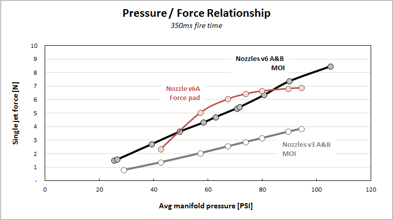
Next I programmed the on-board Arduino to fire the jets for a short interval (350 milliseconds) and measure (1) the angular acceleration using the IMU chipset; and (2) the manifold pressure using the pressure transducer. Knowing acceleration and the moment of inertia, we can back-solve for jet force using Newton's Second Law for rotations (or Euler's equation if you prefer). Knowing the instantaneous pressure, we can also quantify the relationship between pressure and force.

Results:

As expected, the results were much more robust than those from the force-sensitive resistor. Although we saw some instantaneous force pad readings over 8 newtons, after a careful (3rd-degree polynomial) curve fit, the true pressure / force relationship measured by the pads is shown by the red line below. According to the jet nozzle math - thank you, thermodynamics - the relationship should be almost linear. Clearly, the force pads exhibit a pronounced non-linearity, despite my best attempts to calibrate around the non-linear response.

The black and grey lines, on the other hand, show the pressure / force relationship from our new and improved method based on measurement of the moment of inertia. I think this is some impressively clean data given that we're basically dealing with a lab apparatus made of plywood and fishing line!

The black line is for the nozzles v6 A&B, where A&B denote two copies of the same design. The design intent for v6 was 11N thrust at 100 PSI. AT 100 PSI we're seeing 8.04N thrust, which is 73% of design intent.

The grey line is for the nozzles v3 A&B. The design intent for v3 was 7.5N thrust at 100 PSI. At 100 PSI we're seeing 4.12N thrust, which is 55% of design intent.


Why is the force lower than design intent? I think there are two answers. First, for v6, the design intent really challenges the solenoid valve used for these tests. The valve has a flow coefficient of Cv = 0.65, which is right at the edge of the 0.64 required by the nozzle math. Any negative variance around the nominal 0.65 means the valve is not supplying all the air that the nozzle can take, and force would be lower as a result. I think this is very likely as the valve is a cheap consumer model.

Second, the specific 3D printer we used for the nozzles has a worst-case dimensional tolerance of +/- 0.2mm. Therefore, the nozzle throats could be up to 12% smaller than designed. This would reduce the mass flow and therefore the jet force.

These two factors could easily explain the failure to achieve the force as per design intent. The good news is, it doesn't really matter! What we really need is an accurate characterization of the pressure / force relationship for each nozzle, which we've clearly got from the graph above. We can plug the equation for those lines (as determined by linear regression) directly into the controller software. It's like a golfer with a perpetual slice - if the slice is perfectly repeatable, that golfer can win championships. He'll always know exactly where the ball will go.

There's another piece of good news I learned from this exercise. My original design intent of 11N or even 7.5N was excessive. We don't need that strong of a jet force. At more than a few newtons the jets spun the test apparatus violently - too violently if you're trying to take nice smooth video. That implies a few things:

  • We can fly the HAPP with manifold pressures well below 100 PSI, possibly in the range of 40-50 PSI. 
  • We can therefore adopt the amazingly lightweight and fast-response Festo MHJ series valves. These valves also have integrated relays, so we can eliminate a separate electronics board.

Why did I over-estimate the necessary jet force by a factor of 2 or 3? Because my original guess of the HAPP's moment of inertia (before anything was designed or built) was way too high. I told you in a previous post that I had very little feel for MOI, and I wasn't lying!

Next: A big milestone.... the first controlled rotations. Cool video coming up!


Friday, May 27, 2016

Who are my readers?

Quick detour:

I just checked the blog stats to see if anyone's been reading. Whoever you are, you don't leave many comments or +1s, so I figured I was talking to a vacuum (no problem, I can take it!).

Well, somewhat to my surprise, I've had 9,449 readers this week. I thought I'd show you the stats for reader geographies:


In honor of the Pakistanis taking the top spot, here's a song by the Pakistani group Strings. Yes, it was actually used in Spiderman 2...


Also FYI: Top platform was Android with 57% and top browser was Chrome with 59%.

Come on guys, leave some comments - don't be shy :-)

Thursday, May 26, 2016

Measuring moment of inertia - Two methods

In the last post I described the trifilar pendulum apparatus for measuring moment of inertia (MOI). The controls software requires MOI as an input parameter so it can calculate the phase plane trajectories. Without knowing the MOI, the flight control computer won't know how much the jets will cause the HAPP to rotate - the jets would be "firing blind" so to speak.

I also explained that once we know the MOI, we can solve backwards and find the jet force produced by the 3D-printed nozzles. This may be more accurate than the jet force measurements we did with the force-sensitive resistor pads on the static test fire stand. An accurate value for jet force is also required by the control system.

So how'd it go?

Using the Arduino-based IMU sensor package and software sketch I developed, it was easy to identify the period of oscillation for the prototype HAPP hardware loaded onto the pendulum platform: 2016 milliseconds. Using this period, and plugging in the physical dimensions of the test setup, I got a moment of inertia around the z-axis (J_zz) of 0.1815 kg-m^2. Stepping carefully through the various measurements I calculated a margin of error of +/- 0.9%. That's pretty tight, and it validates my guess that we could get error percentages in the low single digits.

Personally, I don't have a good "feel" for moment of inertia. Answer quickly: Within a factor of 10 (or even 100), what's the J_zz of a typical passenger car? Couldn't tell you unless I looked it up. Similarly, it's hard for me to see the number 0.1815 kg-m^2 and judge if it's even approximately correct. Can we validate it with another method? It doesn't need to be super-accurate - within 20% or 30% would be fine - just close enough that we know the trifilar pendulum method is more or less correct.

Meet Mr. Rubber Band. From Hooke's Law we know that the pulling force exerted by this band will be more or less proportional to how far it's been stretched. I used one of the trifilar pendulum's hanging scales and measured pull force for different amounts of stretch to obtain the following relationship. The black line is data and the red line is a linear fit - pretty tidy for some rough data.


Now we have a known force that we can apply tangentially to the HAPP arm as shown in the picture below. By measuring the resulting acceleration with our on-board IMU instrumentation, and then applying our old friend the Euler equation for rotations, we can back-solve for J_zz, the moment of inertia.


The HAPP project utilizes only the most
sophisticated technologies: Cardboard box,
millimeter scale, and an old rubber band.
Nozzle v6 points left and v3 points right.

I expected this method to be fairly sloppy, but after several trials, the average J_zz measured by Mr. Rubber Band's test was 0.1839 kg-m^2. That's only a 1.4% difference versus the nominal value from the elaborate trifilar pendulum method! Conclusions:
  1. The pendulum method is good.
  2. The pendulum method was a lot of work that wasn't really necessary!
  3. I never would have believed the rubber band results if that's all I had, so perhaps the pendulum wasn't a total waste of time :-)
Of course we'll have to come back and measure J_zz again once the HAPP has been fully constructed. We'll also need to measure moments of inertia along the other two principle axes, as well as the three cross-axis products of inertia, thereby filling out the inertia tensor. But at least we've validated the trifilar pendulum method pretty thoroughly.

Next post: Characterizing the relationship between jet force and manifold pressure.