The business end of a cold gas reaction control system is the nozzle. The HAPP will need twelve of them (see Controls Part 2).
As rocket nozzles tend to be fairly complex shapes with internal cavities, and also as the HAPP nozzles will likely be fairly small, it seems natural to fabricate them using additive manufacturing techniques, a.k.a. 3D printing. 3D printing requires a CAD model of the object to be printed, so again (like I did for the controls simulations) I needed to upgrade my 1990s skill set and learn some modern CAD software.
I started with FreeCAD. It's a fairly easy-to-learn parametric modeling package, and did I mention that it's free? I used FreeCAD for the first two nozzles I printed, but on the recommendation of my local printer, ThingSmiths in Ann Arbor, I switched to Autodesk Fusion 360 for all the subsequent nozzles. Fusion 360 also has the excellent price of $0.00 but is more highly polished and integrated into the cloud. This greatly facilitated sharing of model data with ThingSmiths.
So how do we design a nozzle? The one piece of trivia related to nozzles that I knew before starting the HAPP project is that nozzles are optimized to work at certain altitudes. The best design for operation at sea level is not optimal for use in the vacuum of space. This is one reason why many rockets are staged; the first stage uses low-altitude nozzles, and the upper stage(s) use high-altitude nozzles. We want the HAPP nozzles to be optimized for atmospheric pressure at the balloon apogee, hopefully around 30Km altitude. That will give us the best control where it counts the most: for the high-altitude money shots.
Atmospheric pressure at sea level is about 14.7 PSI. At 30Km it's 0.2 PSI which is almost a space-like vacuum. Because it may be difficult to test the HAPP flight nozzles in operating conditions - that is, unless someone wants to lend me a vacuum chamber! - my general idea went like this. Develop the nozzle design equations and draw some designs that are optimized for various altitudes. Print a few. Test and verify that the performance at sea level - namely the thrust - matches up with the theoretical equations. If everything lines up, we can have confidence in the math and use it to design the high-altitude flight nozzles. So here we go...
The type of nozzle we need is called a converging-diverging nozzle. If designed correctly it can drastically accelerate the gas to many times beyond the speed of sound. The nozzle's shape resembles its name. It takes the gas and squeezes it down through a narrow throat (converging flow), and then it expands the gas until it reaches the nozzle exit (diverging flow). Look at the classic shape in the image of the Saturn V's F-1 engine below: hot gas starts at the top, gets rammed down through the narrow throat, and then expands down through the exit.
"Designed correctly" means a few things. First, the mass flow has to choke at the throat. Gas velocity at that point will be exactly Mach 1. Second, the gas from the throat must be expanded such that gas pressure at the nozzle exit is equal to the ambient atmospheric pressure. Contrary to what you might guess, the gas will not slow down as it expands - it will accelerate tremendously. Third, the curved profile from throat to exit must be of a certain shape and length to enable efficient expansion.
The thermodynamics get a little tedious, but I came across some useful summaries from NASA, Robert Braeunig, and Richard Nakka. Also see MIT, Purdue, and Georgia Tech. Follow those links if you're interested in the math.
In short, my design process went like this:
Below are a few of the design iterations. Version 1 is a high-altitude nozzle designed to produce 11 newtons of thrust using air supplied at 100 PSI. In the photo (not the CAD), notice the threads tapped into the top of the chamber inlet. This was to enable insertion of a threaded tube connector. It's a reasonable design, but I cracked the first printing when I over-torqued the connector. Also notice the tessellation (little "triangles") inside the chamber and nozzle. This is due to my not knowing I could specify a finer-resolution mesh when exporting the data for 3D printing; it wasn't immediately obvious in FreeCAD.
Version 3 is a low-altitude nozzle for 7N thrust using air at 100 PSI. Note the extended inlet tube. This enables use of a threadless quick-connect for the supply tube - thanks to the Oregon State team for sharing this idea via email! Also note how I mounted it on a pusher plate so I can place on a force-sensitive resistor pad and measure jet force during static test firing. This is a converging-diverging nozzle; you can just barely see the narrow throat a few millimeters back from the exit.
Version 6 is a low-altitude nozzle for 11N thrust using air at 100 PSI. Again there is a quick-connect tube. But now the nozzle base has been optimized to sit directly on the force resistor pad. It's far too bulky to serve as flight hardware, but I'm sure I'll be printing a few more design revs before launch :-) Some cool statistics: The math says this nozzle should have an exit velocity of Mach 1.9 and a mass flow rate of 22.9 grams of air per second. It really blows!
So we have one nozzle for high-altitude operating conditions (v1) which we can only test at low altitude, and two different design intents for low altitude (v3 and v6). In the near future I may add a nozzle that's optimized for helium instead of air or N2; it can potentially produce higher thrust, and I may use helium for the reaction gas instead of air as we'll have lots of helium on-hand when we fill the weather balloon on flight day. With this collection of nozzles, we can physically test the validity of the math over a variety of conditions and have confidence the flight versions will work as predicted.
Finally, regarding the 3D printing - these nozzles were printed on a modified Formlabs Form1+ SLA printer with 25-micron resolution. The material is Formlabs Clear methacrylate photopolymer.
Next post: Figuring out the pneumatic system and solenoid valves...
As rocket nozzles tend to be fairly complex shapes with internal cavities, and also as the HAPP nozzles will likely be fairly small, it seems natural to fabricate them using additive manufacturing techniques, a.k.a. 3D printing. 3D printing requires a CAD model of the object to be printed, so again (like I did for the controls simulations) I needed to upgrade my 1990s skill set and learn some modern CAD software.
I started with FreeCAD. It's a fairly easy-to-learn parametric modeling package, and did I mention that it's free? I used FreeCAD for the first two nozzles I printed, but on the recommendation of my local printer, ThingSmiths in Ann Arbor, I switched to Autodesk Fusion 360 for all the subsequent nozzles. Fusion 360 also has the excellent price of $0.00 but is more highly polished and integrated into the cloud. This greatly facilitated sharing of model data with ThingSmiths.
So how do we design a nozzle? The one piece of trivia related to nozzles that I knew before starting the HAPP project is that nozzles are optimized to work at certain altitudes. The best design for operation at sea level is not optimal for use in the vacuum of space. This is one reason why many rockets are staged; the first stage uses low-altitude nozzles, and the upper stage(s) use high-altitude nozzles. We want the HAPP nozzles to be optimized for atmospheric pressure at the balloon apogee, hopefully around 30Km altitude. That will give us the best control where it counts the most: for the high-altitude money shots.
Atmospheric pressure at sea level is about 14.7 PSI. At 30Km it's 0.2 PSI which is almost a space-like vacuum. Because it may be difficult to test the HAPP flight nozzles in operating conditions - that is, unless someone wants to lend me a vacuum chamber! - my general idea went like this. Develop the nozzle design equations and draw some designs that are optimized for various altitudes. Print a few. Test and verify that the performance at sea level - namely the thrust - matches up with the theoretical equations. If everything lines up, we can have confidence in the math and use it to design the high-altitude flight nozzles. So here we go...
The type of nozzle we need is called a converging-diverging nozzle. If designed correctly it can drastically accelerate the gas to many times beyond the speed of sound. The nozzle's shape resembles its name. It takes the gas and squeezes it down through a narrow throat (converging flow), and then it expands the gas until it reaches the nozzle exit (diverging flow). Look at the classic shape in the image of the Saturn V's F-1 engine below: hot gas starts at the top, gets rammed down through the narrow throat, and then expands down through the exit.
"Designed correctly" means a few things. First, the mass flow has to choke at the throat. Gas velocity at that point will be exactly Mach 1. Second, the gas from the throat must be expanded such that gas pressure at the nozzle exit is equal to the ambient atmospheric pressure. Contrary to what you might guess, the gas will not slow down as it expands - it will accelerate tremendously. Third, the curved profile from throat to exit must be of a certain shape and length to enable efficient expansion.
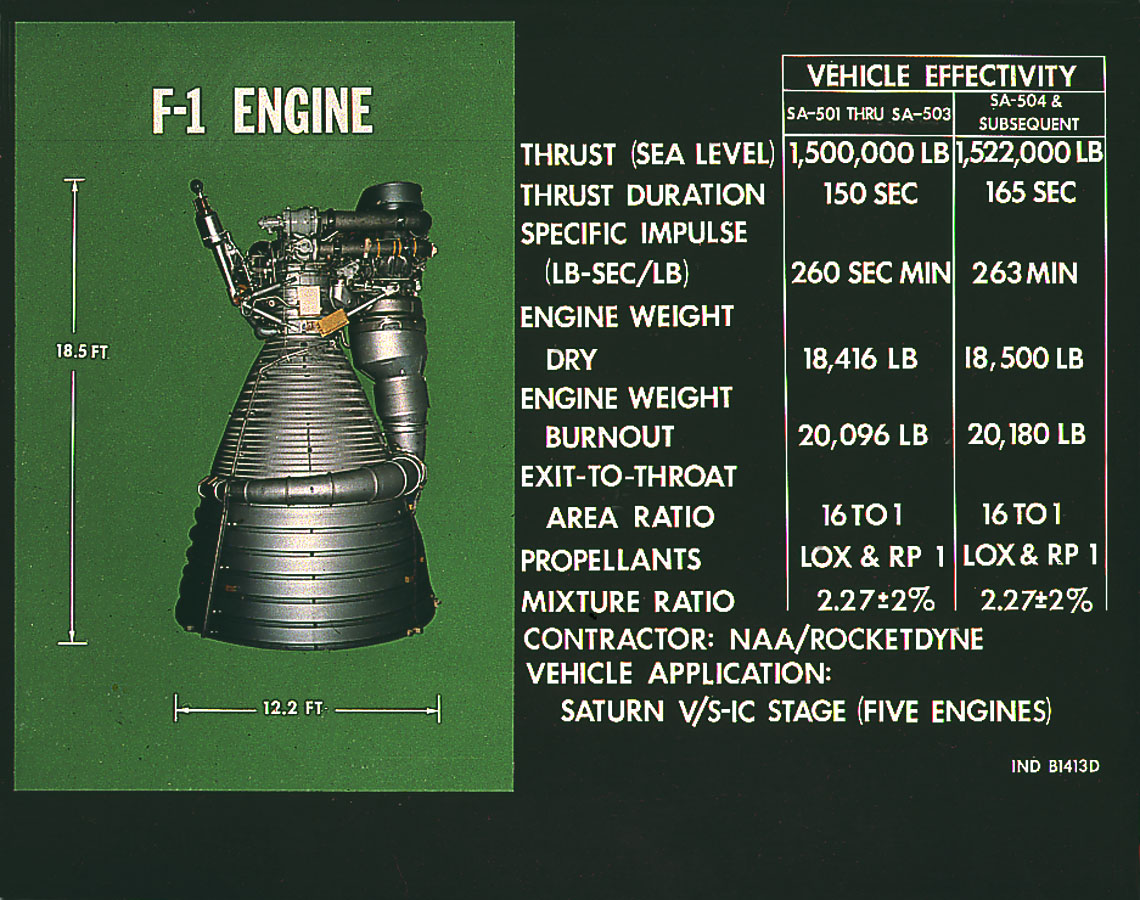 |
| Rocketdyne F-1 engine for the Saturn V. Beast mode! |
The thermodynamics get a little tedious, but I came across some useful summaries from NASA, Robert Braeunig, and Richard Nakka. Also see MIT, Purdue, and Georgia Tech. Follow those links if you're interested in the math.
In short, my design process went like this:
- Choose operating conditions - altitude, gas composition, temperature, supply pressure from tank. The final design will target an altitude of 30Km using N2 or helium gas at 100 PSI. We'll probably use a thermal blanket inside the HAPP to protect batteries and electronics, so assume temp is 20C.
- Choose desired thrust force. 11 newtons is a good target based on the controls simulation. With my best guess at the HAPP's inertia tensor (having not yet designed it!), 11N should settle the HAPP out of a hard spin in about 3-4 seconds. If that's over-powered for fine stabilization, we'll have to scale things down later.
- Solve for primary nozzle parameters - throat radius, exit radius, nozzle length.
- Apply the nozzle contour method published in 1958 by G. V. R. Rao, one of those Project Mercury-era badasses with a slide rule. Mad respect for that generation of engineers.
- Render the completed nozzle contour into a solid object for 3D printing.
Below are a few of the design iterations. Version 1 is a high-altitude nozzle designed to produce 11 newtons of thrust using air supplied at 100 PSI. In the photo (not the CAD), notice the threads tapped into the top of the chamber inlet. This was to enable insertion of a threaded tube connector. It's a reasonable design, but I cracked the first printing when I over-torqued the connector. Also notice the tessellation (little "triangles") inside the chamber and nozzle. This is due to my not knowing I could specify a finer-resolution mesh when exporting the data for 3D printing; it wasn't immediately obvious in FreeCAD.
 |
| Test nozzle v1 |
 |
| Oopsie |
Version 3 is a low-altitude nozzle for 7N thrust using air at 100 PSI. Note the extended inlet tube. This enables use of a threadless quick-connect for the supply tube - thanks to the Oregon State team for sharing this idea via email! Also note how I mounted it on a pusher plate so I can place on a force-sensitive resistor pad and measure jet force during static test firing. This is a converging-diverging nozzle; you can just barely see the narrow throat a few millimeters back from the exit.
 |
| Test nozzle v3 |
Version 6 is a low-altitude nozzle for 11N thrust using air at 100 PSI. Again there is a quick-connect tube. But now the nozzle base has been optimized to sit directly on the force resistor pad. It's far too bulky to serve as flight hardware, but I'm sure I'll be printing a few more design revs before launch :-) Some cool statistics: The math says this nozzle should have an exit velocity of Mach 1.9 and a mass flow rate of 22.9 grams of air per second. It really blows!
 |
| Test nozzle v6 |
So we have one nozzle for high-altitude operating conditions (v1) which we can only test at low altitude, and two different design intents for low altitude (v3 and v6). In the near future I may add a nozzle that's optimized for helium instead of air or N2; it can potentially produce higher thrust, and I may use helium for the reaction gas instead of air as we'll have lots of helium on-hand when we fill the weather balloon on flight day. With this collection of nozzles, we can physically test the validity of the math over a variety of conditions and have confidence the flight versions will work as predicted.
Finally, regarding the 3D printing - these nozzles were printed on a modified Formlabs Form1+ SLA printer with 25-micron resolution. The material is Formlabs Clear methacrylate photopolymer.
Next post: Figuring out the pneumatic system and solenoid valves...
No comments:
Post a Comment