Monday, January 30, 2017

Passing 35,000

Back in May 2016, I wrote a post describing the geographical composition of my audience as I crossed 10,000 readers. I had every intention of refreshing the data periodically, perhaps as I hit 25,000. Well, I should have checked the stats sooner, as not only did I blow by 25,000, but I should hit 40,000 in a few weeks!

The total today stands at 37,419. As I did back in May, allow me to give some color, followed by some awards to you, my dear readers...

For starters, here are some basic stats:


And here is the geographical breakdown:


Back in May I pointed out the curious (to me, anyway) fact that the highest source of readers outside the USA was Pakistan. Mystery solved: In the description of the blog for Google's search engine, I had included the keyword "bang bang." This is a reference to the particular type of control algorithm I embedded into the flight computer's autopilot function, explained here. It was an innocent but fateful mistake, as folks in Pakistan apparently search for popular Bangladeshi celebrities using the word "bang" followed by a name, and for whatever twisted reason harbored by its nefarious AI, Google was returning a link to the HAPP Blog amidst the search results. I know this to be true because Google shows me the search terms used by those who clicked through to the HAPP blog website!

For those curious, the #1 most searched-for Bangladeshi celebrity by those who also visited the HAPP blog is this lovely person:


Apu Biswas, Bangladeshi actress

Alas, with the "bang" reference deleted, the Pakistanis have fallen out of the Top 5 (although someone apparently has enough spare time to continue visiting the blog). The crown now belongs to France! Here's a special tribute to mark the occasion:


Vive la France!


Finally, I simply must give an honorable mention to a recent newcomer on the list. I have ZERO idea how folks in Oman found this blog, but my dear Omani readers - I salute you!


Monday, January 23, 2017

Cap'n, we need more power!

Now that I've started testing the field of view and placement of cameras - including the primary camera, the stonkin' Nikon KeyMission 360 - I've run right smack into an unfortunate reality: My old PC is useless for editing 4K video. It literally cannot run the editing software without immediately crashing. As the primary goal of the HAPP project is to get 360-degree 4K video and give my dear readers a virtual reality ride to space, this is a pretty big problem.

In addition, I'm having difficulties manipulating the full 3D model of the HAPP in AutoCAD Fusion 360. It crashes frequently and I've lost hours of work. For that matter, the flight control simulations in MATLAB/Simulink are painfully slow.

As I have lots of work remaining in all those areas, it's time to bite the bullet. I'm retiring the PC I built nearly 7 years ago (it was a banger back then!) and building a new rig this week that can handle these tasks.

For those curious about such things, here are the parts I just ordered today:


An 8-core CPU, a screaming graphics card, 64 GB of RAM, 12 TB of storage, and lots of liquid cooling ought to hold me for a while :-)

It sucks to deviate from the parachute-testing plans I had for the coming weekend, but this is a necessary step...

Saturday, January 21, 2017

Tether and camera mount: Initial design

In the last post I described how I learned a hard lesson about taking time to do a thorough engineering analysis when necessary. In this post I'll apply that lesson to a small but critical part of the HAPP: The tether ring, which is where the HAPP is attached to the balloon that will lift it over 30Km into the sky. It turns out that this part is one of the most highly engineered components in the entire project.

From the start of the project I knew I'd need a robust place to attach the balloon. Initially I assumed this would be a simple metal ring of some sort. However, after completing the full 3D model of the HAPP, I decided to integrate two additional functions into the tether.

First, the tether will also serve as the attachment point for the parachutes that will deploy during descent. There's no sense adding additional mass for a completely separate structural element to achieve this function.

Second, the tether will also contain the mount for the primary camera, which is a 360-degree 4K ultra HD camera (specifically, the Nikon KeyMission 360). The only place where the camera will have a mostly unobstructed view of the world is from the top of the HAPP. If I attach the camera to, say, the side of the main strut, then a large portion of the view will be occluded. The camera therefore needs to go at the apex, but it can't interfere with the tether or the parachutes.

After several iterations using 3D printing to verify the geometry (thank you Owen and Steve at ThingSmiths!), I arrived at the following design:


In this rendering you can see a few important features. First, note that the base of the part will insert directly in to the square-section carbon fiber tube I'm using for the main body strut. The rendering shows four of the M3.5 mounting bolts that will go through the strut wall. The bolts are mainly to ensure position while I bond the metal body of the tether to the carbon fiber strut using some specialty adhesive.

One side of the camera - and one of its lenses - is visible in the rendering. This camera is symmetrical and has a second 180-degree fisheye lens on the other side. The camera automatically stitches together the two 180-degree videos to form a 360-degree virtual reality video in all its glory.

You can also see two of the three parachute attachment rings at the ends of short arms that jut out horizontally. There is the main ring enclosing the camera, and finally there is the actual balloon tether ring sitting on top. It's not obvious from the picture, but the parachute rings and camera enclosure are designed to be almost invisible to the camera's field of view. Here's a quick demonstration. In this 360 video, note the kevlar/carbon fiber lower aero shield that I spent the entire summer of 2016 learning to fabricate...


360 camera field of view confirmation.
If this doesn't play on your screen in 360,
try viewing with YouTube here.


What you can't see is how the camera is attached. There's a 1/4"-20 UNC bolt going up into the camera's standard mounting socket. However, as the part will be bonded to the main strut, the bolt must be started and tightened using a long tool inserted from the bottom of the 836 millimeter-long main strut. To facilitate this blind insertion, I added a "docking cone" to the bottom of the part, which is visible below:


Bottom view of tether / camera assembly
showing blind insertion cone for 1/4" bolt.

With the basic geometry defined, it was time to optimize the part for light weight while insuring it can withstand the forces resulting from opening shock of the parachutes. A skinny part is better as it minimizes total weight and maximizes ultimate flight altitude, but more importantly, this part is at the apex of the HAPP and will strongly contribute to a higher center of gravity. This is bad - see my struggles with CG in the last post. Too skinny, however, and the part will fail when the chutes deploy. How to find the right balance?

For this we need some real engineering, and the right tool is finite element analysis. The 3D modeling package I'm using, AutoCAD Fusion 360, happens to have a nice little FEA component that's extremely intuitive and easy to use. To run the analysis, however, we need to know what maximum force we can expect from the parachute opening shock.

I performed the shock analysis by hand using some references from NASA back in the 1960s (the technical gift that keeps on giving!), the Naval Ordnance Lab, and the Naval Surface Weapons Center. I used numerical integration to scale time/force curves given known parameters, yielding a conservative maximum force estimate of 1150 newtons.

If you want to play around with such things and don't feel like rolling your own, I recommend you check out a little piece of software called OSCALC. It gave a worst-case force of 1050 newtons, thereby validating the accuracy and conservative nature of my approach. It also comes with a user manual that walks through some of the math.

The analysis assumes we are using three of these lovely parachutes from the folks at Fruity Chutes. The number and size of chutes was selected to yield a landing speed of 2 meters per second, which is equivalent to being dropped from a height of 0.2 meters. If one chute fails to open, the landing speed will be only 3 m/s, which is still pretty cushy.

With the forces defined, it was time to optimize the design using FEA. I started with a design based on manual calculations using cantilever beam equations. From there, I went through 7 cycles of fine-tuning the design and the choice of materials. Finally I settled on aluminum 7075-T6 and the design shown in the renderings above.

Here's a little video showing the final design after optimization. The amount of deformation is greatly exaggerated - in real life you'd not be able to see it with your eyes. The blue color denotes a high safety factor, and yellow, orange, and red colors denote progressively lower ones. A safety factor of zero means the part is right at the yield strength for the material. I optimized the design so the region with the lowest safety factor is at 0.5 - appropriate given the conservative analysis of parachute forces.


Analysis of safety factors using finite element analysis.
The short video show how the arms deform as
the parachutes deploy.


Same analysis, just a snapshot instead of the video


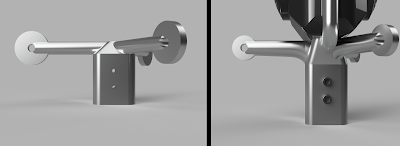
To give you an idea of how the design evolved with the FEA analysis, here's a comparison of the parachute attachment arms from version 1 and the final version 7. The arms got shorter, they changed from a round profile to a variable elliptical profile, and the chute attachment rings got substantially smaller. All of that extra metal was not necessary. Besides changes to the arms, the base portion that inserts into the main body strut got longer. This was mainly to accommodate the cone-shaped feature that assists with blind insertion of the camera mounting bolt.


Evolution of parachute arm
from v1 to v7 using FEA

Final part weight is 139 grams. Currently, the part is being CNC milled out of a single piece of 7075-T6 aluminum by the outstanding team at ProtoLabs.

OK kiddies, this concludes our case study in mechanical engineering for the day. See you next post for some live testing of parachutes!

Sunday, January 8, 2017

Structure: Re-design for center of gravity

Happy New Year, and Happy 1st Anniversary of the HAPP project! It's been a whole year since I decided to undertake this project. It might also seem to have be a year since my last blog update...

There is a reason for my lack of blogging. Well, two reasons actually. The first reason is that I got a new day job in mid-July, and I've been pretty focused on the new gig. Gotta pay the bills for the HAPP project!

The second and more crucial reason is that I hit a roadblock as I started to assembly all the flight hardware, especially the structure. Turns out I had balance issues. Specifically, I couldn't figure out how to package the guts of the HAPP such that the center of gravity was sufficiently low. The CG must be lower than the aerodynamic center of pressure if the HAPP is to remain aerodynamically stable during the free-fall portion of its descent from balloon burst down to the altitude for parachute deployment. If the CG is too high, the HAPP gets tippy.

Think of a shuttlecock - most of the weight is at one end, the nose, and the center of pressure (where the wind catches it) is at the other end, the feathers. This make it stable as it flies. We're trying to achieve something similar with the HAPP, but we want it to be stable with the lower shield facing downward - you may recall that the HAPP is essentially a scale replica of an Apollo Command Module.

The "final" design I've been using was based on some internal packaging that evolved from multiple prototypes, and it relied on some rough hand calculations for the center of gravity. I thought I could roughly calculate the CG accurately enough that some final adjustments after building the main structure would be sufficient to fine-tune the CG. Not so! After weeks of staring at a lab table full of parts, I just couldn't make it work.

To find the solution, I had two options. Option 1 was to keep buying lots of parts and try, try again until I found the answer. This is OK when dealing with plywood and cardboard prototypes. This is not OK when dealing with flight hardware that's primarily carbon fiber - the stuff is expensive!

Option 2 was to model every single part in 3D software and play with the design until I figured it out. This option is cheaper, but requires time to model all the bits and pieces. Every screw. Every panel. Every piece of electronics. Every pneumatic component. All of it.

Having already spent too much money on this project, I went with Option 2. I used AutoCAD Fusion 360, which is an excellent free program. It took some weeks, but I finished the modeling, and I found my solution to the CG issue. It entailed a serious re-arrangement of the HAPP's guts. As a bonus, I was able to cut almost 1 kilogram of weight out of the design. That means higher potential maximum altitudes on flight day.

With the design completed, I have started ordering parts and fabricating the final structure (no really, it's final this time!). In the coming weeks I'll post some photos and videos of the build process. In the meantime, here's a rendering of the section between the lowest deck (the tank deck) and the second deck (the propulsion deck, which supports the pneumatic valves). I omitted the pneumatic hoses and some wiring for clarity. Two of the three canisters holding the main parachutes are just visible at the top of the image.

With the CG roadblock cleared, the project is back on track, and with a hard lesson learned. Sometimes there is no substitute for thorough, quantitative design work before you build!


Valves and low-pressure regulator hanging
down from the Propulsion Deck.
Tanks visible at bottom.

Bonus pic: 3D-printed thruster pack and
quick-connects for air hoses, mounted
on the end of the jet arm